Power System Protection Basics
Jan 21, 2022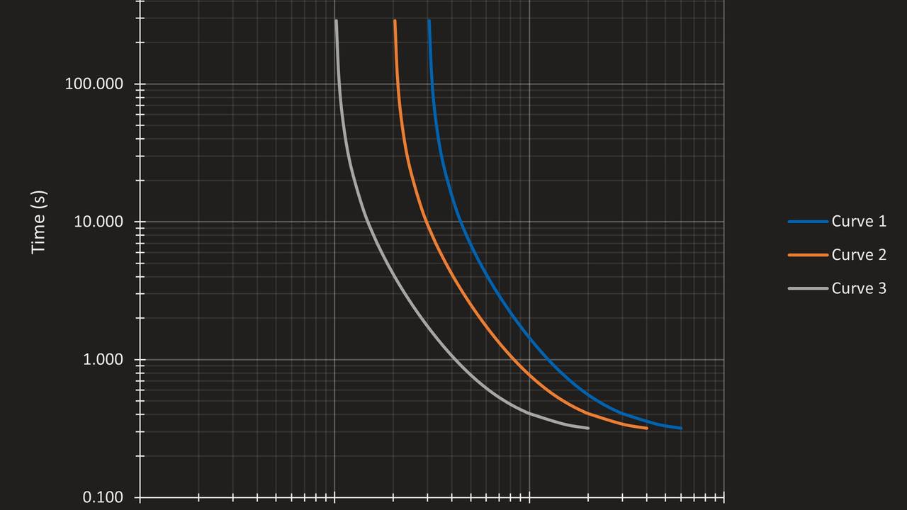
Introduction to Power System Protection
Types of Power System Faults
A power system fault can be defined as an unintentional low impedance connection between different phases, or to ground. When a fault has no impedance (i.e., zero impedance), it is often referred to as a bolted fault. If the fault has impedance in the connections between phases or to ground, it is often referred to as a resistive fault. Resistance in faults can be caused by the object causing the fault (e.g., tree branch) or by the electric arc between the conductors.
Excluding open circuits, which may also be considered faults, there are eleven (11) possible fault combinations:
- Three-Phase (a-b-c)
- Three-Phase-to-Ground (a-b-c-g)
- Phase-Phase (a-b, b-c, c-a)
- Phase-Phase-to-Ground (a-b-g, b-c-g, c-a-g)
- Single-Phase-to-Ground (a-g, b-g, c-g)
Balanced vs. Unbalanced Faults
Of the above faults, three-phase and three-phase ground faults are called “balanced” because they involve all three phases, in which case the system balance is maintained (i.e., voltage and current magnitudes will be (almost) equal, and their phase angles will be 120 degrees apart).
Likelihood of Faults
Statistics vary regarding the likelihood of faults, and they depend on the part of the power system (i.e., generation, transmission, distribution) but an estimate of the likelihood of faults is as follows:
- Three-Phase or Three-Phase-to-Ground: 2%-5%
- Phase-Phase: 5%-10%
- Phase-Phase-to-Ground: 15%-20%
- Single-Phase-to-Ground: 65%-70%
Items to Consider for Power System Protection
A few key items are of importance as it relates to protection: the severity of the fault, whether it involved ground, and whether the fault has resistance.
Severity of faults is an important factor in selection of element pickups. It is also important when assessing equipment ratings. Of specific importance to relaying is the effect of high current magnitudes on CT saturation and relay thermal ratings. Low current magnitudes (usually exacerbated by fault resistance) should also be considered when selecting pickups of elements, to ensure the element is sensitive enough to detect the fault.
Types of Faults and Difference Between Phase and Sequence Components
Symmetrical Components
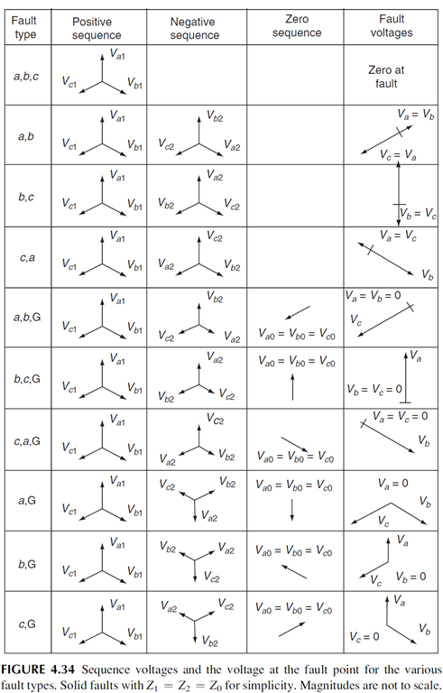
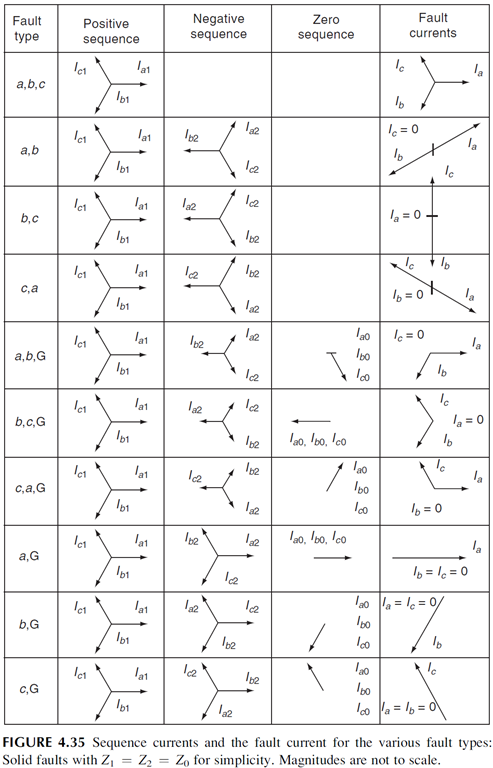
The symmetrical components method is a technique that simplifies the analysis of unbalanced faults by decomposing a set of three-phase unbalanced phasors (as occurs during a power system fault) into three sets of balanced phasors, named the positive, negative, and zero sequence sets. The analysis of unbalanced faults using the symmetrical components technique is much easier, since the sequence networks are mutually independent, and each type of fault has a specific set of sequences it involves.
For example, if a fault involves ground, it will have zero sequence current flow. If a fault is balanced (i.e., three-phase or three-phase-to-ground), it will not have negative or zero sequence current flow. Consequently, different protective element will provide protection for different types of faults. As an example, an inverse-time overcurrent element (51G) will not operate for a three-phase or phase-phase fault, while a negative-sequence overcurrent element (51Q) will not operate for a three-phase fault but will operate for a phase-phase fault. Because of this, it is important to understand how the sequence components behave during different types of faults. The figures below show the sequence voltages and currents during faults:
Phase-Sequence Component Conversion
The following equations can be used to convert phase components into the corresponding sequence components:
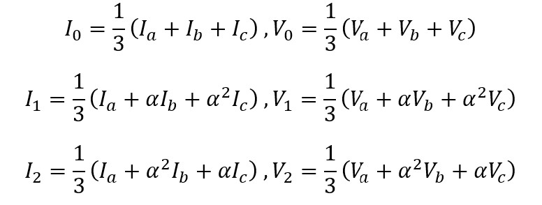
Where α = 1∠120°
Sequence-Phase Component Conversion
The following equations can be used to convert sequence components into the corresponding phase components:
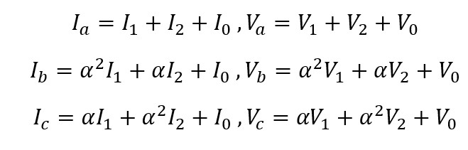
Where α = 1∠120°
Overcurrent Protection
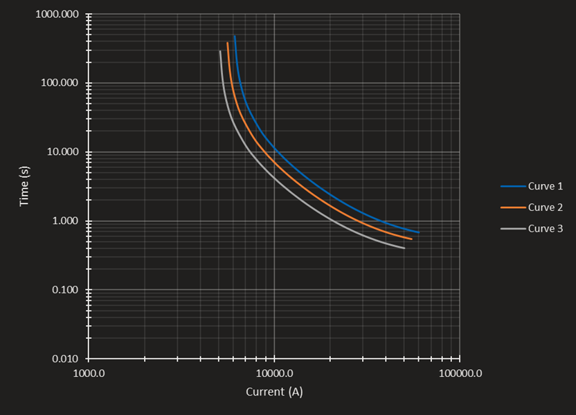
Overcurrent protection is the most widely used form of protection. The so-called inverse-time overcurrent element has a characteristic that makes it trip faster for higher fault currents, while allowing long trip times for low fault currents (or overload conditions). This characteristic resembles the damage curves of equipment such as transformers, motors, etc. In the figure below, three curves are plotted in a time vs. current plot. As can be seen, the trip time is inversely proportional to the fault current magnitude, hence the name, inverse-time overcurrent.
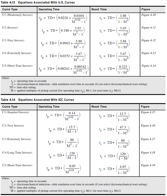
Different manufacturers have different overcurrent operating characteristics. Some of the most widely used curves in SEL relays are the “U” curves. The relay’s instruction manual provides equations for defining the time vs. current characteristic of these curves:
Overcurrent Coordination
When coordinating two overcurrent elements, it is generally desirable that, as we move downstream, the pickup of the overcurrent element decreases. This is to avoid miscoordination for fault currents that are close to the element’s pickup. Similarly, it is often desired to lower the time dial of the overcurrent element to provide faster tripping as we move downstream, although this may not always be needed depending on the type of fault and its magnitude.
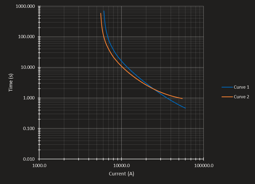
As an example, picture the two overcurrent elements below. Curve 1 has the following settings: 6000A pickup, 5.0 time dial, U3 curve. Curve 2 has the following settings: 5500A pickup, 4.0 time dial, U3 curve. For a fault with 20,000 A magnitude, the coordination margin is about 0.8 seconds. The industry standard is to have a coordination time interval of 0.3 seconds or more. Notice that, as the fault current increases, the coordination margin decreases. Because of this the fault current magnitude must be considered when doing coordination studies.

Of importance here is also the characteristic of the curve. For example, the SEL U3 curve is referred to as a “very inverse” curve, while the U2 and U4 curves are referred to as “inverse” and “extremely inverse”, respectively. In the picture below, the Curve 1 type has been changed from U3 to U4, and the Curve 2 type has been changed from U3 to U2, with all other settings kept the same. Notice that because the curve types have been changed, although the pickup and time dial settings have been kept the same, the curves now miscoordinate at high fault current levels.
Continue learning about power engineering and power system protection and control with our video-based on-demand online courses.
Stay connected with news and updates!
Join our mailing list to receive the latest news and updates from our team.
Don't worry, your information will not be shared.
We hate SPAM. We will never sell your information, for any reason.